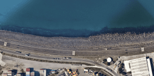
Banksmeadow Revetment – Recollections of a young coastal engineer
by Angus Gordon OAM
In this special article of the Australian Coastal Society, esteemed coastal engineering Angus Gordon reflects on the challenging construction of the Banksmeadow Revetment, a critical piece of coastal infrastructure located inside Kamay/Botany Bay
——————————————————————————————————————————
Background
Following the Second World War there was a progressive increase in the amount of cargo being shipped through the Port of Sydney. At the same time the nature of the ships was changing from the traditional format of cargo being loaded and unloaded manually from the holds of ships, often as individual items or consignments or bulk materials, to increased packaging, containerization of cargo or to specialised bulk material handling facilities. Initially the containerisation of items other than bulk goods promoted using ships with “roll on roll off” (RORs) designs for packaged cargo which was stored on vessels in such a way that enabled containers and or other items such as motor vehicles to be accessed directly by a stern side ramp into the hold of the ship and then moved ashore, or onboard depending on whether it was being delivered or being dispatched. This form of operation did mean the stowage on board needed to be carefully configured so the cargo could be appropriately accessed at the destination port. In addition, containers were developed that enabled shore-based facilities to crane them into and out of the holds of ships. Ship design began to reflect this change and overall port operations became more efficient.
Previously port facilities had often been tied up for weeks while each individual vessel was unloaded with incoming cargo and loaded with outgoing cargo. Over time there was a quantum change from cargo, other than bulk materials, from being stored in holds of ships to an increasing large proportion of the cargo, in appropriately designed containers, being stacked on deck, in multiple layers. This meant that vessels could roam the world with their container load configured in such a way that at any port, the containers destined for that port, could be craned off and any new shipments be craned on without disturbing the rest of the load, a simple logistics exercise. St the same time bulk materials handling was progressively concentrated on specialised ports such as Newcastle and Port Kembla.
However, the increasingly efficient container-based cargo transfer operations still tied up wharves for extended periods of time due to the onshore operations associated with containers being individually delivered to and removed from the destination wharf areas by road or rail transport. To achieve further efficiency, a storage facility at the wharves was required that enabled both incoming and outgoing containers to be temporarily stored awaiting transhipment.
The challenge for Sydney Port
The challenge this brought to the Port of Sydney was that virtually all the waterfront, where the necessary temporary storage areas could be located, was already occupied by commercial, industrial and high value residential development and therefore only available at a high premium. So, the opportunities to improve the efficiency of operations and expand the port facility of Sydney Harbour were limited. Initially it was recognised there was some potential for expansion up the Parramatta River in the vicinity of Homebush Bay and Duck Creek. The problem being however that there were impediments, such as low bridges and shallow water, which would prevent a normal ocean-going cargo vessel from penetrating that far upstream without major change to existing infrastructure. It became clear that in order to utilise the western area of Sydney Harbour it was going to be necessary to unload cargo from the ocean-going vessels into lighters (barges), and have the cargo moved upstream using these shallow draft vessels, propelled by tugs to locations where they could be unloaded ashore. Obviously, this was going to be a slow process with the ocean-going vessels still held up, moored at various locations in the main harbour, while the cargo transfer was taking place. This inefficient and the costly solution of multiple handling was only suitable as a “stop-gap” measure and not a satisfactory solution for the future.
By the late 1950s early 1960s the Maritime Services Board (MSB) who were responsible for and controlled the Port of Sydney, recognising its future as a cargo transfer port was limited, began considering other alternatives. Port Kembla was ruled out as having a limited port area with its outer harbour being subject to seiching and therefore having difficulties with vessels safe mooring while the inner harbour, being quite small and dedicated to bulk handling of materials such as wheat and coal. It therefore provided only a limited opportunity for major expansion to enable it to take over the role of Sydney Harbour as NSW main cargo port. Similarly, Newcastle Harbour had limitations, in particular the underwater rock bar at the entrance meant that the size of vessels that could operate through the port were restricted. There was a major and costly project undertaken in the 1970s to deepen the entrance by blasting the top of the rock bar. While that increased the water depth over the bar, and hence the draft of vessels that could enter and leave the port, the on-going increase in world ship sizes meant that the rock bar soon again became a limitation.
The emergence of Port Botany
The MSB, in reviewing the options for potential ports in NSW and taking into account the areas where cargo was likely to be sourced from, or destinations where it was to go to, determined that Botany Bay was the most likely candidate to enable expansion of the Port of Sydney Harbour, and even potentially take over the role from Port Jackson.
At about the same time as the MSB had started its deliberations, the Commonwealth Government recognised that the east/west runway at Mascot airport was experiencing air traffic limitation and could not readily be duplicated. So, the Commonwealth Government determined there was a need for a new runway. They recognised that any new runway would need to have a north-south orientation and therefore, because of site limitations, extend out into Botany Bay thereby requiring protection against wave action (Foster and Dudgeon, 1970). To some degree this airport solution was the catalyst for considering the development of a new facility in Botany Bay to address the need for port expansion. Examination of transport links demonstrated that the logical location for any new port facility was in the northeast corner of the Bay.
The principal challenges for constructing a Botany Bay port facility were:
- No facilities or deep-water areas for shipping,
- Insufficient room for the shore-based handling facilities,
- A low lying and swampy shoreline and back shore area,
- The area of the Bay being considered was exposed to ocean wave attack through the entrance.
These issues meant that, any new cargo port and handling facility would require a significant degree of land fill and need to be sheltered behind a breakwater or revetment built out into the bay. In addition, a dredged channel configuration would need to be constructed along with wharves and berths to enable shipping to access the proposed port.
Concept development
While the new Mascot north-south runway was being developed by the Commonwealth utilising the Water Research Laboratory of the University of NSW as its specialist advisors, the MSB engaged the British Hydraulics Research Station at Wallingford in England for the port design.
The initial concept was that the design would allow for the port to be progressively expanded and eventually take over the cargo handling role from Sydney Harbour. For this to be achieved a new large land base would need to be created for the interim storage of containers and other cargo awaiting transhipment and tanks for liquid products being exported or imported through the port. Given that for ships to access the port berths, a considerable amount of dredging of both the navigation channels but also the berth areas were required. This dredged material could be used to create the new land base required for container and other cargo handling/temporary storage areas.
To manage the exposure of the site to storm wave activity, a critical aspect of this port development was the construction of a large, 1400m long revetment on its seaward side to protect the reclaimed area. This revetment needed to be capable of absorbing ocean wave attack from waves coming directly through the entrance, recognising that the energy of these ocean waves would be exacerbated by the deepening of the bay from the entrance to the port to enable shipping to safely access the port.
The navigation channel including the deepening of the entrance to Botany Bay at the Heads, along with the reclamation of a significant area behind the revetment, required the development of a dredged area configuration that accommodated the additional exposure to wave energy entering the bay by redistributing it around the bay. Areas such as Towra Point were at the time identified as “wastelands” that could absorb some of this re-distributed energy.
Basic Design criteria for the revetment
Revetments are constructed to protect shore-based assets. Hence the key issue for design is that of understanding the acceptable level of damage the asset being protected can reasonably tolerate, that is, the acceptable risk. Risk is defined to be the product of “likelihood” of damage and the potential “consequences”. Reversing this conventional risk equation in the case of Banksmeadow, the key factor is the consequence of failure of the revetment. Given the quantity of cargo, liquid storage and valuable infrastructure that the revetment was to protect, and the critical role the new port was to play in the economy of NSW, it became apparent, at an early stage, that the potential consequences were such that any failure of the revetment was unacceptable and hence “likelihood” was not a consideration. The revetment had to be designed to successfully weather any attack. This somewhat simplified the design criteria. Basically, the revetment needed to be capable of resisting any waves that could enter the port through the heads and able to manage any overtopping by the largest waves.
Wave hindcasting at the time suggested that in major storms this area of the NSW coast could experience extreme storm waves from the east to south sector with a “significant” height of 10m to 12m (Stone and Foster, 1967) and a maximum wave height up to double the significant wave height. The associated wave periods could be 12 to 14 seconds.
With the then “ruling depths” at the entrance these extreme waves would break before entering the Bay. However, with entrance dredging larger waves than previously could possibly enter the Bay. Water depth at the entrance, as well as in dredged areas, was an important design criterion. Hence the dredged pattern would determine the seabed configuration in front of the revetment and the wave attack and wave overtopping potential along the length of the revetment which progressively extended into the deeper water of the bay.
In developing the design criteria wave refraction, diffraction shoaling, and reflection studies were required to establish the appropriate design conditions to be met along the revetment and to document the possible impacts on other areas of the Bay. Interestingly reflection was included as it was felt that some waves reflected off the revetment could be re-reflected, albeit in a reduced form, from nearby shorelines like those at Yarra Bay and Frenchmans Bay.
The water depth for the design was conservatively taken as the sum of the proposed water depths post dredging taken at Indian Springs Low Water (ISLW), plus the peak spring tidal range, plus the potential extreme storm surge (wind and barometric pressure set-up). This analysis yielded a potential significant wave at the most exposed section of the revetment of 8.2m. Wave setup was not taken into account as it was considered likely to be minimal given the configuration of the Bay and associate rivers, hence the potential dissipation of any increase in water depth due to breaking waves causing mass transport.
It is important to note that while there was no allowance for any future alteration in wave conditions or water levels due to climate change as in the late 1960s/early 1970s the concept of climate change was not part of conventional thinking. In fact, it wasn’t until 1991 that Engineers Australia developed guidelines for the consideration of climate change in the design of coastal structures (Gordon et al, 1991). However, it was decided at the time the design was being undertaken that because of the critical nature of the port infrastructure being protected model testing of the revetment design should include runs with model waves representing up to 10m prototype (Gordon, 1972) as this was considered to be the maximum wave that could enter the Bay.
The Design
The design was based on the conventional practices of the time (CERC, 1973). These included progressively forming up the overall shape underlying the revetment using the reclaimed sand as the “core” material, and then armouring the vulnerable sand shape with “filter layers” followed by secondary and then primary armour. The filter layers consisted of increasingly coarse gravel and rock sized to retain the material directly below each layer. The filter cloth (geotextiles) used today did not exist at the time, so this complex and time-consuming use of “filter layers” had to be employed. This meant the sand core was vulnerable until each of the layers was in place and protected by the secondary and primary armour layers. The role of secondary armour is not only to retain the filter layer structure and provide increased porosity by establishing a drainage path for waves as they run up the revetment, but also the opportunity to establish a relatively uniform foundation for the primary armour. At the time the standard design criteria was for the secondary armour to be a tenth of the weight of the primary armour (CERC, 1966) and was seen as potentially providing some protection should small failures develop in the primary armour and hence the opportunity to undertake post storm repairs.
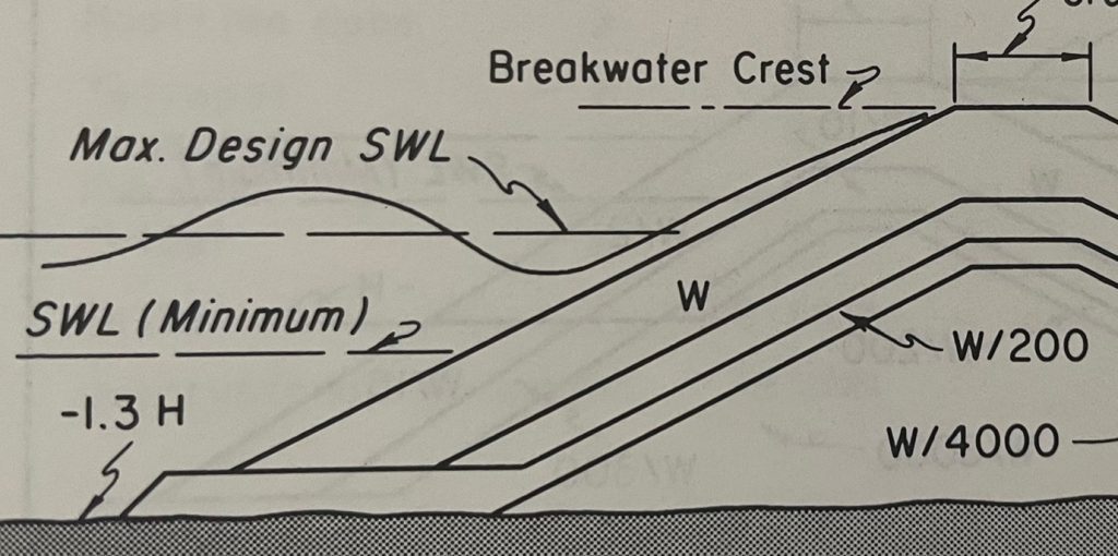
A sometimes poorly understood issue with concrete armour units is that they are not reinforced as reinforcing deteriorates with time. Saltwater penetration of the concrete causes it to break apart as the reinforcing rusts and expands. Therefore, concrete armour units, while seeking through their shape to maximise the ability to resist wave attack, need to be sufficiently robust to survive in an unreinforced form. The earliest shapes of concrete primary armour were square, rectangular and pyramidal shapes, none of which showed particularly efficient interlocking characteristics and hence had a relatively high potential for failure (CERC, 1966). At the time the Banksmeadow revetment was designed, the number of alternative designs for concrete primary armour was rapidly expanding, although only a few of the more sophisticated designs had been “field tested” for robustness. In addition, many of the earliest designs developed to improve their interlocking were conservatively shaped and rather stubby, but still with relatively low resistance to damage.
The most economic design of revetments generally features rock as the outer (primary armour) layer(s). However, as the exposure to wave attack increases it becomes difficult to find suitable sized rock, and even more challenging to deliver it to a site and place it on the revetment slope. For exposed situations like that of the Banksmeadow Revetment the size of primary armour required to resist wave attack made rock primary armour impractical and hence the need to consider artificial concrete armour units as an alternative.
Tribars artificial concrete armour units were developed in Hawaii by Palmer (Palmer, 1960) and were one of the first of the then rapidly growing numbers of the more sophisticated types of concrete primary armour units. Practical experience suggested they were a robust and efficient design suitable for the type of exposure the Banksmeadow Revetment could experience. However, Tribars are a complex shape which require equally complex formwork. To cast each Tribar the formwork has be bolted together, carefully filled with concrete to ensure there are no voids and then once the concrete has set the formwork stripped, oiled and bolted back together for casting the next unit. Multiple sets of formworks are required to speed up the production process, but it is still a time-consuming task. Because of the slow production rate and the need to allow the newly cast units to stand for an extended period of time so they could develop full strength, there is the need to have a large casting yard with sufficient storage so that the supply of units can meet the demands of a revetment’s advancement.
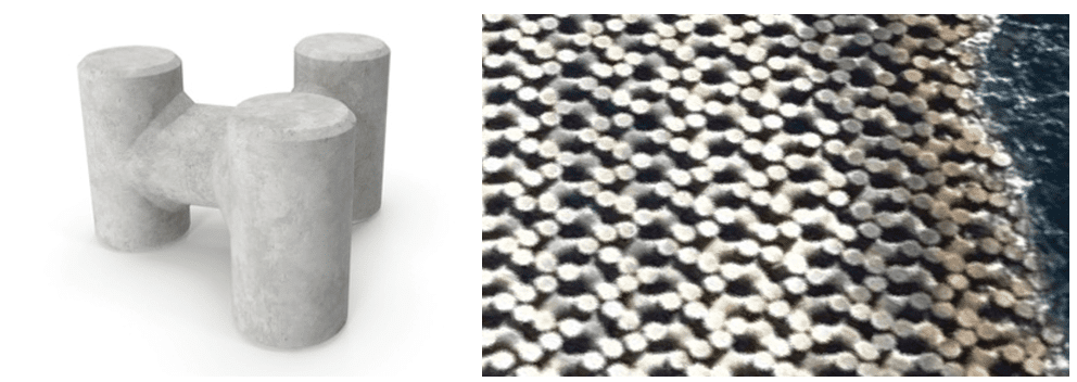
Tribars also require a relatively uniform secondary armour surface. The three legs of each Tribar must be in contact with the slope, and each unit is at the same angle to the overall slope as its neighbouring units. This is an often challenging and time-consuming requiring manipulation of the secondary armour under each Tribar leg. It becomes significantly more challenging when Tribars are to be affixed to the underwater sections of revetment and divers are required to both “trim” the secondary armour and manipulate each Tribar into position.
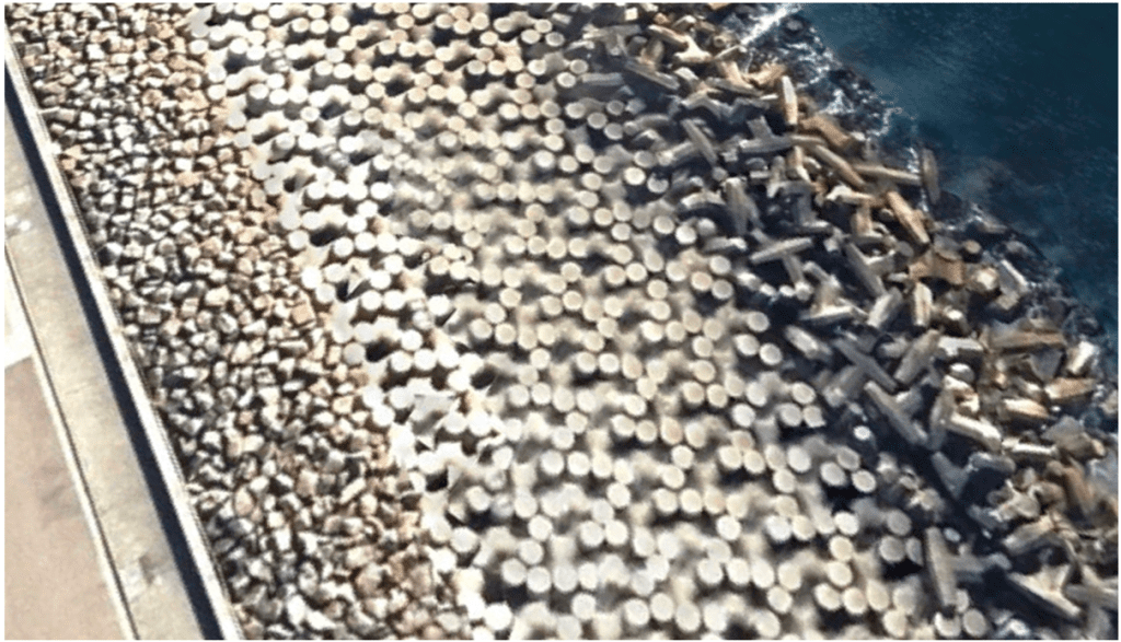
Regardless of these difficulties but taking into account the then new Mascot runway extension into the Bay had been designed with a Tribar primary armour, Wallingford proposed a solution which involved a conventionally designed revetment armoured by concrete Tribar units on a 1 vertical to 2 horizontal slope. The Tribars were sized based on the exposure of the revetment slope to wave attack from 2.5T inshore to 5T then 10T as exposure increased to eventually 20T for much of the main section of the revetment. The Tribars not only protected the revetment slope but also the toe of the revetment. This toe was a bulked-up feature at the bottom of the slope to accommodate any future subsidence or scour of the seabed directly in front of the revetment.
The initial design called for the Tribars to be placed on the secondary armour as a single layer in a random configuration. One problem emerging from this was that the 20T units were found to not necessarily be adequate for extreme storm events. The UNSW Water Research Laboratory, when designing the Mascot runway extension, had found it could significantly increase Tribar susceptibility to damage if Tribars were placed in a pattern which resulted in leg-to-leg contact of adjacent units.
WRL was therefore contracted by the MSB to review the original design and propose adjustments. The leg-to-leg contact configuration was model tested for the Banksmeadow Revetment situation which was considerably more exposed than the runway extension. It was found that the 20T units were adequate with the new configuration of placement, however, underwater placement issues remained. So, WRL investigated the replacement of the Tribar toe armour with 2 layers of concrete cubes. While testing showed this could overcome the placement problems, the toe was less stable and so recommended further consideration of an alternate armour unit for the toe.
Along with this review WRL re-assessed the height and design of the revetment. In particular its crest in order to prevent or manage overtopping. Again, physical model testing was used to finalise a design in which the primary armour extended to the height of the revetment determined, from the testing, necessary to prevent overtopping. However, given the potential consequences of damage, a very conservative approach was adopted in which at the crest the secondary armour extended horizontally landward as a porous crest terminating at a modest concrete recurve “wave” wall backed on the port side by a sealed roadway surface with drainage to cope with any overspray.
The storm that caused a re-think
In May and June 1974 Sydney was exposed to the worst storms in recorded memory (Foster et al, 1975). Because of the complex construction method and the multiple layers of filter material, the section of the revetment that was then under construction but had not yet had the final 20ton Tribar armour units fitted, suffered significant damage. As a result, approximately 700 metres of the revetment had to be reconstructed.
This highlighted the need to review and expedite construction methodology. WRL was again asked to suggest a more efficient way forward. By this time the range of concrete armour units coming onto the world stage was rapidly increasing. One was the Dolosse unit developed in South Africa by Merrifield (Merrifield and Zwamborn, 1966). Like the Tribars the Dolos required complex form work and so production was slow and difficult. At the time Dolos, which look like a double anchor, have a number of advantages. Studies undertaken at WRL demonstrated a 16T Dolos randomly placed in a double layer could achieve the same resistance to damage as the 20T pattern placed Tribars. However, they were far more easily placed on the slope both because of the reduced weight and also because there was not the need for the same degree of finish on the secondary armour layer, which could also be of a reduced size. The ease of placement was particularly relevant to the underwater placement and hence the fully formed slope could advance at a far more rapid rate.
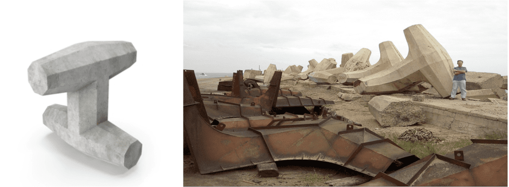
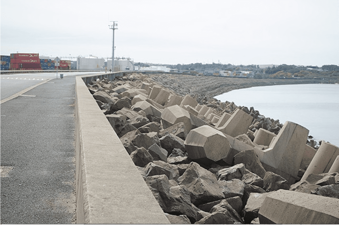
Thus, there was a switch from Tribars to Dolos. But a stockpile of Tribars existed in the casting yard. Following further physical modelling tests the decision was taken to have a hybrid solution in which Dolosse were used for the underwater sections of the slope from the toe and up to high tide level. Tribars were continued to be placed on the above water slope. Hence the reasons for the varying configuration of the revetment armouring.
At the time Dolos were a relatively new armour unit and so their vulnerability to breakage was not fully appreciated. Over time it has been found that Dolos are unfortunately somewhat fragile and can experience reduced effectiveness due to fracture. Fortunately, since 1974 the revetment has not been exposed to extreme wave action and certainly not that considered in the 1970s design criteria, so the revetment has been stable. This has tended to result in an assumption that the revetment is a permeant structure without necessarily questioning its ability to resist a major storm event. Nor has adequate consideration been given to the issue that even unreinforced concrete in maritime structures have a “life” of 50 to 60 years, as defined by the codes.
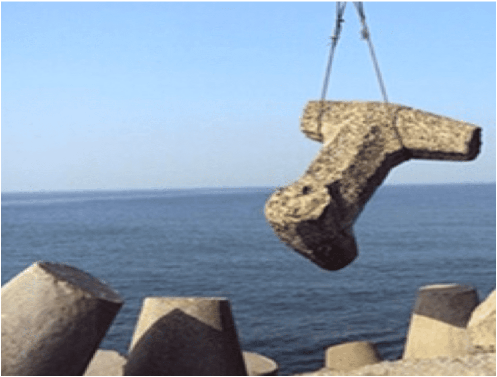
As Banksmeadow Revetment armour was placed almost 50 years ago it would seem timely to undertake a major review of its condition and in particular the wave impact zone of the Dolos and the underwater region as well as the section exposed to regular wetting and drying.
Dredging
As previously highlighted, the new Botany Bay Port required extensive dredging of the bed of the Bay. This included the dredging of the navigation channel from the entrance to the port area and deepening of the port in the vicinity of the berths. As with the north-south airport runway extension the material required to construct the required area of reclamation for the port came from dredging the bed of Botany Bay.
Wallingford’s solution for managing any increase in wave energy entering the Bay due to entrance deepening was, in addition to dredging the navigation channel, to dredge a fan shape in the seabed which would spread the energy out into the main area of the bay. This dredged pattern was in part designed to direct some of the excess energy onto the revetment, that was to be designed accordingly. It also directed increased wave energy onto the Silver Beach area at Kurnell where a series of groynes were proposed to manage any increase in shoreline instability and erosion in front of the residential housing. As mentioned, any impact on Towra Point was considered to be of no consequence at the time. Instead of being seen as an important ecological National Park it was identified as a “swampy waste land”. It was recognised that there may be some impact on Yarra Bay and Frenchmans Bay as a result of reflected waves from the revetment. However, it was felt this could be best assessed once the revetment was constructed and could again be handled by construction of groynes.
An overlooked and unintentional outcome
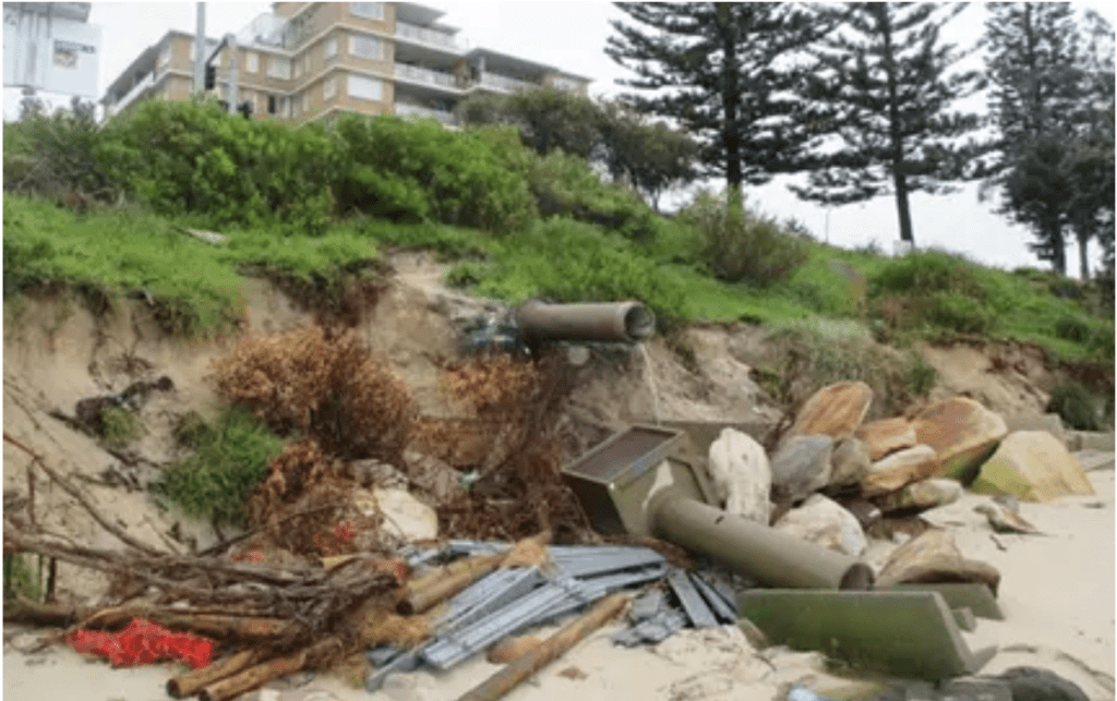
Little consideration was given to the potential impact on Lady Robinsons Beach in the far west of Botany Bay. This beach had been impacted by the dredging undertaken to generate the fill material for the airport runway extension which, as demonstrated by studies undertaken by WRL, directed more wave energy onto Lady Robinsons. What was unappreciated, or ignored, at the time, was the overall change in wave climate for Lady Robinsons Beach. This has resulted in the change of wave fetches for locally generated wind waves resulting from the change of form of the Bay, produced by the significant reclamation works associated with both the runway extension and the port reclamation. The issue at Lady Robinson Beach is that it is a long narrow formation in which the change in wave climate, particularly the locally generated wind wave climate, has created a significant coastal process imbalance. This has resulted in an east to west net littoral drift eroding the foreshore and delivering sand into the entrance of Georges River. The construction of groynes and some sand nourishment programs have failed to overcome this imbalance and so the foreshore and main road remain vulnerable.
References
CERC (1966) “Coastal Engineering Research Centre Shore Protection Planning and Design”. U.S. Army Coastal Engineering Research Centre, Technical Report No. 4, Third Edition, June 1966.
Foster, D.N. and Dudgeon, C.R. “Model Studies of Sea Wall for Mascot Runway Extension” University of New South Wales Water Research Laboratory Technical Report 70/6, 1970.
Foster, D.N., Gordon, A.D. and Lawson, N.V., (1975).“Storms of May-June 1974, Sydney”, N.S.W. Proceedings 2nd Australian Conference on Coastal and Ocean Engineering, Institution of Engineers, Australia, Publication 75/2, Gold Coast, Queensland, April 1975:1-11.
Gordon, A.D. (1972) “Breakwater Stability Revetment Botany Bay”. University of New South Wales Water Research Laboratory Technical Report 72/11, 1972.
Gordon, A.D., Lawson, N.V. and Wilkinson, D.L. (1991) “Guidelines for Responding to the Effects of Climatic Change in Coastal Engineering Design”. National Committee on Coastal and Ocean Engineering, The Institution of Engineers, Australia, 1991 ISBN 85825 564 2.
Merrifield, E.M. and Zwamborn, J.A (1966) “The Economic Value of a New Breakwater Armour Unit ‘Dolos’ “. 10th Proceedings Conference on Coastal Engineering, Tokyo, September 1966, Vol. 11, pp 885-912.
Palmer, R.Q. (1960) “Breakwaters in the Hawaiian Islands” Proceedings of the American Society of Civil Engineers, Waterways and Harbours Division Vol.86, No. WW2, Paper No. 2507June 1960 pp 39-67.
Stone, D.M. and Foster, D.N. “Data Provided for NSW Coastal Engineering Works” Australian Civil Engineering and Construction, April 1967.

